éRüDThe operating states of the respective modes
ü@The operating mode of the high-frequency
AC link DC-AC converter has inverter mode
and rectifier mode. The steady state of rectifier
mode can be classified into 12 Mode. But
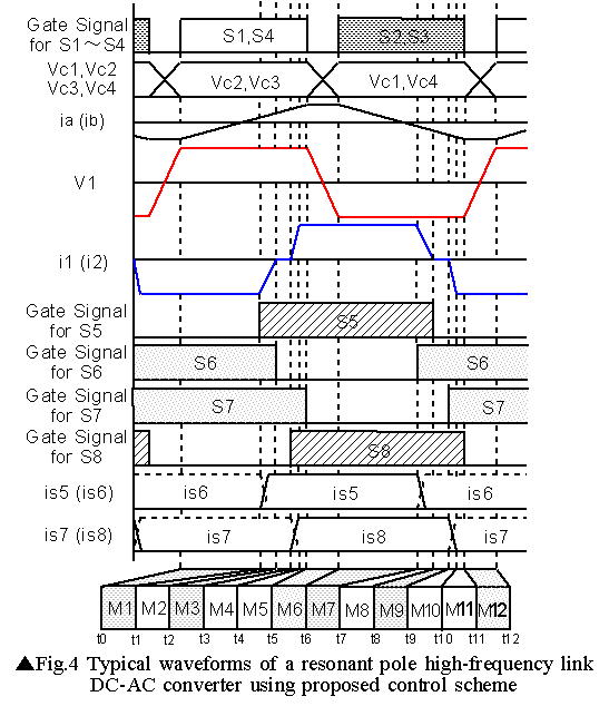
we will explain the operations at steady
state from Mode 1 to Mode 6 by using the
operating waveform shown in Fig.4, because
the operation of that interval makes no difference
with from Mode 7 to Mode 12. The equivalent
circuits corresponding to the times (t0 to
t6) and modes (M1 to M6) of Fig.4 are shown
in Fig.5. For simplicity, the power devices
are ideal switches that have zero switching
time and switch on and off instantaneously.
The circuit is also assumed ideal, with no
internal resistances and stray capacitances.
However, the leakage inductances of the high-frequency
transformer are considered in order to utilize
them in ZCS operation on the secondary side.
ü£Mode 1 : power regeneration intervalü@
(t0üģtüāt1)
ü@ At this time, S1,D1,S4,D4,S6(D6),S7(D7)
are on, and the power regenerated from secondary
side to primary side via D1,D4,S6(D6),S7(D7).
Only very small resonance current of resonant
pole flows on S1 and S4. This state will
continue until switch S5 is turned off at
any time t1.
.jpg)
ü£Mode 2 : ZCS commutation intervalü@(t1üģtüāt2)
ü@At time t1, when S5 is on, Io begins commutation
from D6 to D5, since D5 becomes forward bias
and D6
becomes reverse bias. At this point, hard-switching
or sudden commutation due to the leakage
inductances of the high-frequency transformer
will not occur, and S5 will be turned on
by soft-switching of the ZCS mode, in which
this current gradually commutates. Since
S6 will be turned off after D6 will be completely
turned off, it will be turned off by ZVS
and ZCS.
.jpg)
ü£Mode 3 : single circulation intervalü@
(t2üģtüāt3)
ü@ When S5 will become on completely, load
current Io flows via S5(D5),S7(D7), resulting
in a single circulation interval. In this
interval, since the primary and the secondary
are separated in circuit terms, there active
power of load will be processed on the only
secondary side. At that time, the power does
not regenerate forward to the primary side.
At this point, only resonance current continuously
flow on S1,S4 in primary side. In practice,
exciting current of high-frequency transformer
will flow in i1, but since its value is essentially
very small, its effect will not present a
problem. Secondary phase-shifted PWM control
scheme controls the output voltage to sinusoidal
wave of cycloconverter by controlling this
interval.
.jpg)
ü£Mode 4 : ZCS commutation(ZVS preparation)ü@
interval (t3üģtüāt4)
ü@At any time t4, for S1,S4 turn off easily,
there is need to flow on S1,S4 in a slight
term. And then, S8 will turn on at t3. When
S8 will be turned on, since D7 will become
a reverse bias, load current Io is commutated
from D7 to S8(D8) by ZCS similarly to Mode
2, and S7 will be turned off by ZVS and ZCS.
.jpg)
ü£Mode 5 : power supply intervalü@(t4üģtüāt5)
ü@When S8 are on, this converter operates as
power supply interval in an instant, since
direction of i1 turns over and it flows via
S1 and S4. At this point, since S1,S4 are
already on, ia and ib flows. So that, di/dt
is relaxed because i1 dose not suddenly flow
in. And after that, at time t5, S1,S4 will
turn off. Let me add, since this interval
is very short in one period, its effect of
regenerating operation will not influence
in particular. When S1,S4 will turn off without
this interval, since i1 will be regenerated
via D1, D4, it flows in the direction which
is such as to demote the charge of C1, C4.
In this case, for reliable ZVS, there is
need to flow the resonance current which
is larger than regenerated current i1 on
resonant pole part. This resonance current
had been become a factor increasing fixed
loss. However, in the proposed scheme, since
i1 flows to S1,S4 once by preparing this
interval, i1 flow forward to a direction
which is such as to promote the charge of
C1, C4. That is there is no need of large
resonance current. Hence, the effect of reduced
fixed loss of secondary phase-shifted control
will not ruin.
.jpg)
ü£Mode 6 : ZVS commutation (quasi-resonant)
intervalü@(t5üģtüāt6)
ü@At time t5, when S1,S4 are off, a quasi-resonant
state occur and C1,C4(C2,C3) start to charge(discharge).
Vc1 and Vc4 increase linearly, and when they
reach the dc source voltage E, i1 commutates
to D2,D3. Therefore S1,S4 will be turned
off by ZVS. S2,S3 will turn on, during i1,ia,ib
will flow via D2,D3. And the half cycle is
completed here.
Thus, by operating the proposed switching
pattern, the soft-switching operations of
ZVS or ZCS, or ZVS and ZCS. In addition,
the proposed scheme can be realized in all
switching with no loss of the features of
the secondary phase-shifted control scheme.
Moreover, it can be reduced fixed loss and
conduction loss.
.jpg)
 Back ü@ü@Topü@ü@Next
Michihira lab. TOP