éSüDThe characteristic evaluations and discussion
ü@Verification of the proposed high-frequency
AC link DC-AC converter was carried out by
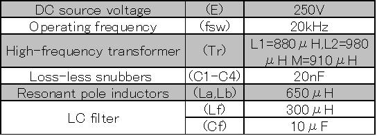
simulation analysis. The parameter values
of the circuits used in the simulation are
shown in Table1. The obtained operating waveforms
of the output voltage and output current
of the high-frequency inverter are shown
in Fig.6. Fig.6(a)is the waveform employing
the conventional control scheme and Fig.6(b)
is the waveform employing the proposed control
scheme. It can be understood from these waveforms
that the output current of the conventional
DC-AC converter is always flowing(positive
or negative). However, the output current
of the proposed DC-AC converter is flowing
a only power supply interval and no flowing
in another interval. This result confirm
that the operation as described in the preceding
section has occurred. In order to realize
high conversion efficiency, the output current
of the inverter had better diminish because
conduction losses of the high-frequency transformer
and power devices are caused by the output
current. From Fig.7(b), since the proposed
DC-AC converter is no flowing unnecessary
current, reduction of conduction losses and
enhancement of efficiency may be achieved.
üźTable.1 Circuit parameters for simulated
analysis
.jpg)
.jpg)
ü@The waveforms of output voltage and current
of the DC-AC converter are shown in Fig.7. Next, the AC output waveforms (100V,60Hz)
of the DC-AC converter are shown in Fig.7.
These figures show output voltage and current
when the load of the DC-AC converter is connected
with inductive load (R=8āČ,L=8mH) and capacitor
input type rectifier load (Cd=1000ā╩F). It
is evident from these figures that the output
voltage of the DC-AC converter is controlled
satisfactory by proposed control scheme even
if reactive power is generated or the output
current is changed suddenly. The last, to
confirm the reduction of conduction losses
in the proposed control scheme, let us calculate
the conduction losses by using the simulation
results. In order to calculate the conduction
losses, we assumed that the saturation voltage
Vfs of the IGBT is 2.2V and the forward voltage
drop Vfd is 1.2V of the diode from the date
sheets of the IGBT modules. And the winding
resistances are assumed as 0.74 āČfor both
primary and secondary, from the measured
values of the high-frequency transformer
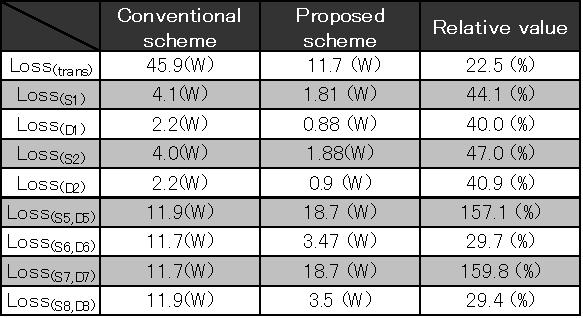
that was used. As a result, calculated conduction
losses while one cycle of high-frequency
inverter is shown in Table.2. It can be understood
from this table conduction losses of each
part is reduced by employing proposed control
scheme. Especially, conduction losses of
high-frequency transformer and power devices
in primary circuit can be reduced by half.
Moreover, the total conduction losses while
one cycle of DC-AC converter in the proposed
control scheme can be reduced to about 81%
compared to the conventional control scheme.
As a mentioned above, the reduced conduction
losses effect and control response of the
proposed control scheme is evident. Thus,
to apply the proposed control scheme to DC-AC
converter is very effective for enhancement
of conversion efficiency and control response.
.jpg)
.jpg)
üźTable.2 Comparative conductive loss of
two DC-AC converter
 Back ü@ü@Topü@ü@Next
Michihira lab. TOP