éQüDSecondary Phase-Shifted PWM Control Scheme
The circuit configuration of the high-frequency
AC link DC-DC converter using secondary phase-shifted
PWM control scheme (below called "proposed
control scheme") is shown in Fig.1.
This circuit is composed of the high-frequency
inverter, the high-frequency transformer,
the diode rectifier circuit and the LC filter.
A difference between conventional DC-DC converter
and proposed DC-DC converter is two power
devices are newly connected inside the diode
rectifier circuit. Fig.2 is shows its switching
pattern, inverter output voltage waveform
and output current waveform. In conventional
control scheme, the converter output voltage
was controlled by giving phase-difference
between the right and left arms of the full-bridge
inverter on the primary side. In proposed
control scheme, the converter output voltage
is controlled by giving phase-difference
between the primary side and the secondary
side which is synchronized with the primary
side. From this reason, between the right
and left arms of the full-bridge inverter
don't have phase-difference. Namely, it operates
as a square-wave generator like a symmetrical
drive with 50% duty including dead time.
By using proposed control scheme, secondary
switches S5 and S6 are both off during the
circulation interval (t1<t<t2) in which
the power is not supplied form the primary
side. At this point, the circulating current
will flow only the secondary circuits via
the high-frequency transformer. Therefore,
the circulating current can not flow on the
primary side (this state is called "the
self circulation interval"). As a result,
almost conduction losses are eliminated because
circulating current can be removed. This
is the distinctive feature of proposed control
scheme. In addition to this, all power devices
can operate under soft-switching condition,
independent of changing load resistance.
From these reasons, the conversion efficiency
become high compared with conventional DC-DC
converter because proposed control scheme
can effectively solve the problems mentioned
above.
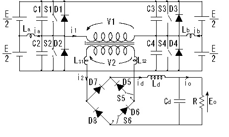
Fig.1. Circuit configuration of high-frequency
DC-DC converter

Fig.2. Switching pattern of secondary phase-shifted
PWM control scheme
 Back ü@Topü@ü@Nextü@
ō╣ĢĮīżŗåÄ║TOP